Prince 60's Reverb AA1164 Build
I'm building the Prince 60's Reverb AA1164 and thought I would share the process. Starting with the BOM and part numbers I ordered.
This page is also a repository for all the useful YouTube clips & Articles I come across. The best thing about building your own amp is that you can always go back in and improve on your creation. I would also like to give credit to those content creators who put so much time and effort into their videos.
But first a disclaimer, follow at your own risk, build at your own risk.
Edit 02JUL25 Disregard my mains wiring in the photos on this thread (the tag strip for the mains will be removed, dedicated mains earth with M4 screw will be added to the chassis and better separation of the primary & secondary PT wires to be tidied up).
I'm about to re wire the mains and PT wiring after watching the Video just released by Rift Amps Mains Wiring - What are the requirements?
Also a good reference article by Rod Elliott on "How to Wire a Power Supply" that contains info on the mains connections, switch, fuse and earth.
https://sound-au.com/psu-wiring.htm
Always learning.
Parts were purchased from Mouser Electronics and some from Mojotone. Power transformer and Output transformer were purchased localy from Evatco.com.au
A good video I found on how to navigate the Mouser web site was published by Psionic Audio on Youtube
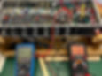
Populating the chassis


Lead dress on the power transformer will be tidied up later. Brass grounding strip installed.
Over to D-Lab for a video on making a ground plate.
I will attempt to follow the wiring colour code as per REC-108-A


18 AWG for the 6V6 tube sockets then 22AWG for the remainder of the wiring. RG174 for Input Jack Signal

I incorporated tip #2 & tip #4 from Terry at D Lab. Brass Ground Plane & Power Distribution Terminal Strips
https://youtu.be/PSAOaPnzGEY?si=Vk59XsFEemET1H4Y
Over to Chris The Guitar Amp Tech for a video on bias & lowering the B+ Also placing a load on the Reverb input when the tank is not connected.
Two guides for first powerup can be found on the Stew Mac & Mojotone web sites using the build guides for their Princeton Reverbs.
Double check the polarity of the filter caps. ;)
The bias pot can be measured and turned full CW before first power up. Check again during the power up checks before installing the power tubes.
Bias resistance high thus more negative voltage so colder bias. (Voltage chart uploaded, see link below the scope picture).


Same bias setting but with volume on 7. The start of clipping.

I was seriously considering the Weber 10F150T 8 Ohm Light Dope but postage to AUS was more than the cost of the speaker.

Two recommendations for this speaker from Lyle and Brad
Time to start building the cabinet. But nothing fancy.


Done! Next Project?
20AUG25 Update,
Amp was working fine but developed feedback. This included a microphonic PCB and wire going to Pin 7 of V3. Moving the intensity knob past one would put the amp into feedback overdrive. (If that is the right description). I checked every component and every connection, all good. Then reached out to a local Guitar Amp Tech who pointed out my rookie mistake. Swapping the output transformer wires on V5 & V6 pin 3 solved the issue. Instead of a NFB loop I had a positive feedback loop. (Positive Feedback from the Negative Feedback circuit) Simple fix and a learning outcome. (Thanks Chris)
Then I decided to swap out the 5AR4 Rectifier for the 5U4GB. This gave me 408V DC PV Pin 3 to GND.
Bias set to:
Inner Tube 20.10 mA 8.2W 63.1% (6V6GT Electro Harmonics 13W ?)
Outer Tube 21.02 mA 8.6W 66%
Sine wave on the scop looks perfect with no crossover distortion. DC voltage on the plates of the 6V6GT's is closer to the Fender AA1164 schematic of 410 V DC.
Two websites that I have found helpful:
http://www.brieskorn.de/int/index.html Go to the Guitar & Amps tab, Amp Projects, or straight to this http://www.brieskorn.de/int/Guitar___Amps/Amp_Projects/AA1164/aa1164.html
The circuit diagram is broken down into the different stages. He also has a Cabinet Building Plan.
And Rob Robinette https://robrobinette.com/AA1164_Princeton_Reverb.htm for mods and original Fender circuit diagrams.